D38999 Mil Spec Connector Guide
D38999 Mil Spec Connectors Explained

Learn how to decode D38999 Part Number. Learn More
Review D38999 insert arrangements. Learn More

Learn about the different shell sizes, styles and finishes. Learn More
Learn how to assamble D38999 connectors. Learn More
What are the different sizes of D38999 connectors? Learn More
What are the different keyway polarizations of D38999 connectors? Learn More
Part Number Breakdown
D38999 Part Number Breakdown.
Assembly Instructions
D38999 assembly instruction.
Part Number Index
List of MIL_DTL-D38999 part numbers.
Introduction
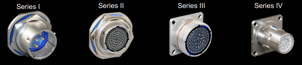
Previously known as MIL-C-38999, MIL-DTL-38999 connectors come in four series: Series I, Series II, Series III and Series IV. They are environmentally resistant connectors that use removable crimp contacts and have an operating range of -65 to +200°C.
Series I connectors are bayonet coupled and have high-vibration properties. They are scoop proof and are ideal for heavy wind and moisture environments. They are utilised when a fast disconnect coupling system is required.
Series II connectors are bayonet coupled, are non-scoop proof, and have a low profile, so are used when weight or space is limited, or in low-vibration, high moisture, and strong wind situations.
Series III connectors are coupled by a quick screw Tri start thread, are scoop proof, and are best suited for normal mating and unmating applications and can be used in high temperature, moisture, wind, or vibration environments when used with the correct accessories. Series III connectors are most commonly use in Military and Aerospace designs.
Series IV connectors are coupled by a Breech-Lok mechanism, are scoop proof, lightweight and suitable for blind mating applications, and they also have high-vibration attributes. They are well suited in high wind and moisture environments when used with the appropriate accessories.
| 38999 | Coupling | Scoop Proof | Durability | High Impact Schock | Bend Moment | Price |
|---|---|---|---|---|---|---|
| Series I | Standard Bayonet | Yes | 500 | Yes | 650 lbs in | $ |
| Series II | Low-Profile Bayonet | No | 250 | No | 150 lbs in | $ |
| Series III | Triple Start Threded | Yes | 500 | Yes | 1000 lbs in | $$ |
| Series IV | Breach-Lok | Yes | 500 | Yes - Heavy | 1000 lbs in | $$$ |
MIL-DTL-38999 Specifications and Datasheets

The most recent MIL-DTL-38999 specification can be downloaded from Defense Logistics Agency Land and Maritime website: click here to download.
Major manufactures of D38999 connectors include Amphenol, TE Connectivity, Glenair, Souriau, Conesys, ITT Cannon and Eaton. You can download each manufacturer's datasheets using links in the following table.
| Manufacturer | Datasheet | |||
|---|---|---|---|---|
| Series I | Series II | Series III | Series IV | |
| Amphenol | ||||
| Conesys | ||||
| Eaton | ||||
| Glenair | ||||
| ITT-Cannon | ||||
| Souriau | ||||
| TE Deutsch | ||||
Part Number Breakdown
D38999 Part Number Decoder Tool
Try our Part Number Decoder Tool! Enter any D38999 part number in the box below and we will decode it for you. We already entered the "D38999/" prefix so you don't have to.
D38999 connector part numbers are composed of six sections in addition to the D38999 prefix:


The meaning of the codes in each section is explained below.
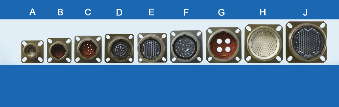
Shell Type

| Series III | Series IV | Shell Type Description | ||
|---|---|---|---|---|
| D38999/20 | D38999/40 | Receptacle, Wall Mount Flange | ||
| D38999/21 | D38999/41 | Receptacle, Box Mount, Hermetic | ||
| - | D38999/42 | Receptacle, Box Mount | ||
| D38999/23 | D38999/43 | Receptacle, Jam Nut Mount, Hermetic | ||
| D38999/24 | D38999/44 | Receptacle, Jam Nut Mount | ||
| D38999/25 | D38999/45 | Receptacle, Solder Mount, Hermetic | ||
| D38999/26 | D38999/46 | Plug, EMI Grounding Fingers | ||
| - | D38999/47 | Plug | ||
| D38999/27 | D38999/48 | Receptacle, Weld Mount, Hermetic | ||
Shell types 26, 46 and 47 are plugs. All other shells are receptacles. Odd numbered receptacle shell types denote hermetic construction: 21, 23, 25, 27, 41, 43 and 45.
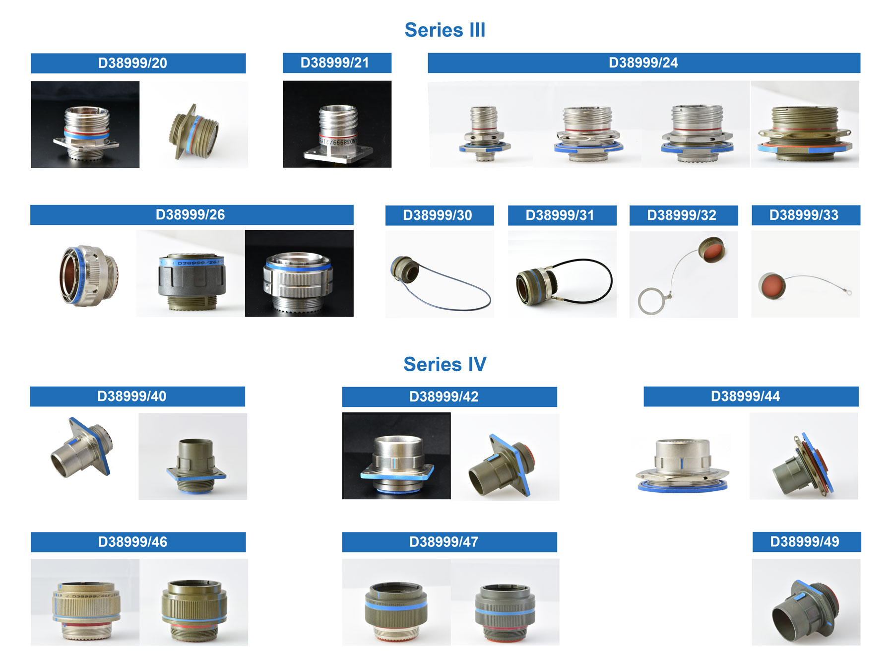
Examples of different D38999 shell styles
Material and Finish

| Code | Image | Material | Finish |
|---|---|---|---|
| F | Aluminum | Electroless Nickel Plated (48-hr. Salt Spray) | |
| G | Aluminum | Space-Grade Electroless Nickel (48-hr. Salt Spray) | |
| H | Hermetic | Space Grade | |
| J | Composite | Olive Drab Cadmium (2000-hr. Salt Spray) | |
| K | Stainless Steel | Corrosion-Resistant Stainless Steel - Firewall (500-hr. Salt Spray) | |
| L | Stainless Steel | Electrodeposited Nickel (48-hr. Salt Spray) | |
| M | Composite | Electroless Nickel Plated (2000-hr. Salt Spray) | |
| N | Hermetic | Stainless Steel, Nickel Plated | |
| S | Stainless Steel | Nickel Plated (500-hr. Salt Spray) | |
| T | Aluminum | Nickel PTFE (500-hr. Salt Spray) | |
| W | Aluminum | Olive Drab Cadmium (500-hr. Salt Spray) | |
| Y | Hermetic | Stainless Steel, Passivated | |
| Z | Aluminum | Black Zinc Nickel (500-hr. Salt Spray) |
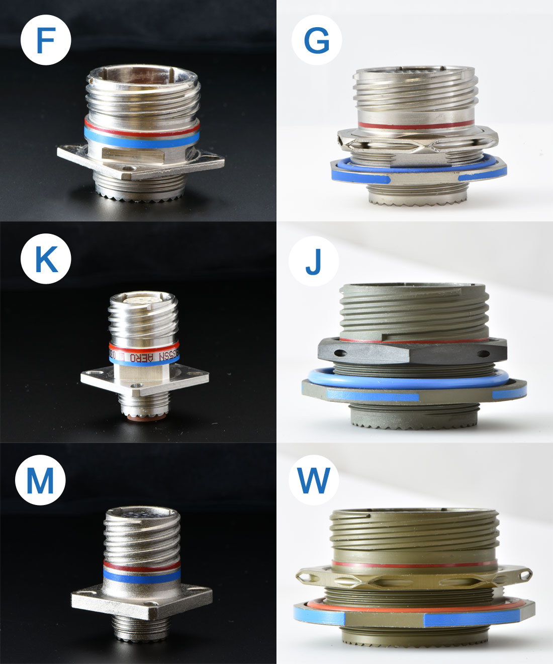
Examples of D38999 finish materials
Shell Size

D38999 connectors are available in 9 shell sizes.
D38999 connector shell sizes: A, B, C, D, E, F, G, H ,J
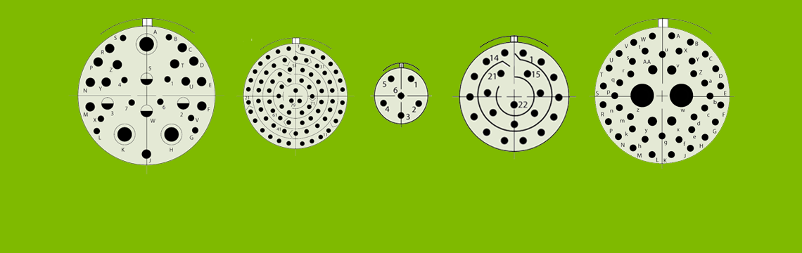
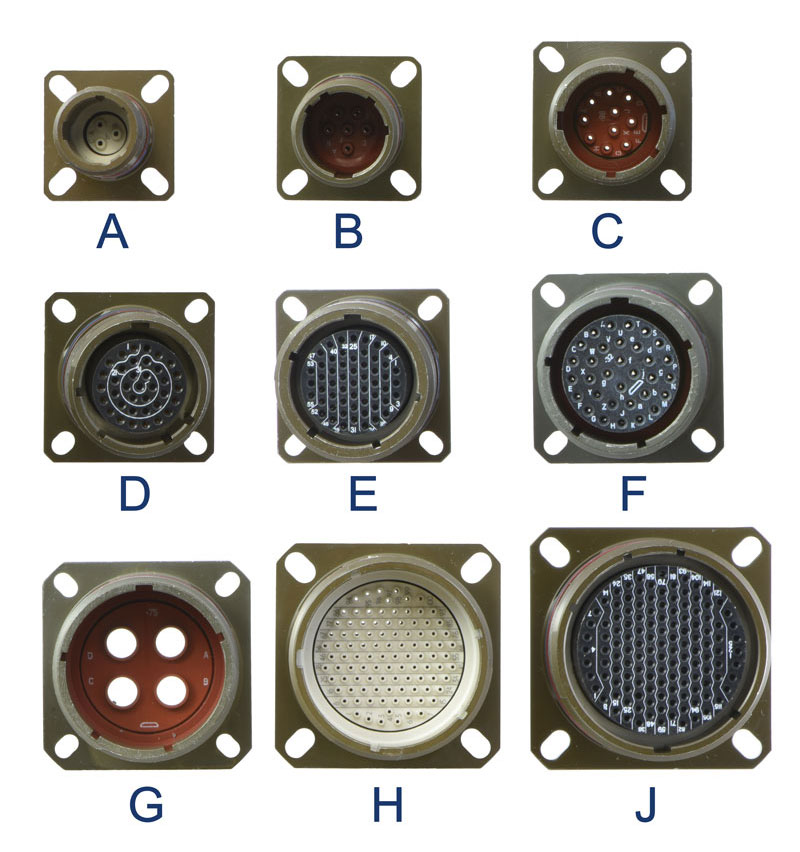
Insert Arrangement

MIL-STD-1560 Insert Arrangements
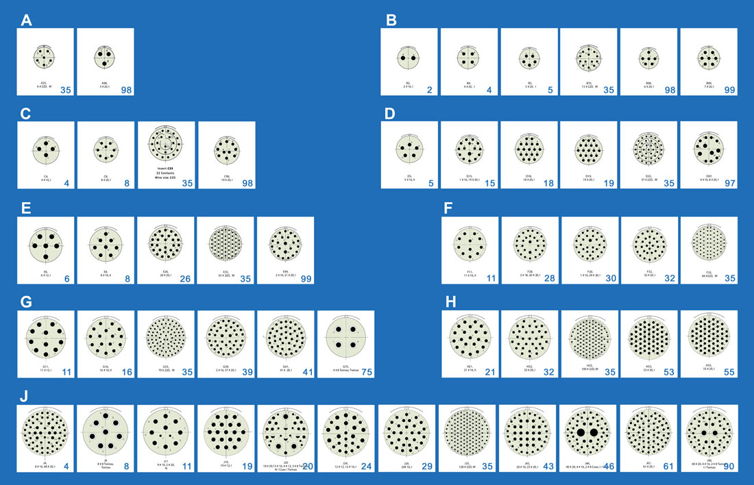
Connector Pin Counts
| Shell Size and Insert Arrangements | Number of Pins | ||||
|---|---|---|---|---|---|
| D38999 Series III | Service Rating | 22D | 20 | 16 | 12 |
| A35 | M | 6 | |||
| A98 | I | 3 | |||
| B2 | I | 2 | |||
| B4 | I | 4 | |||
| B5 | I | 5 | |||
| B35 | M | 13 | |||
| B98 | I | 6 | |||
| B99 | I | 7 | |||
| C4 | I | 4 | |||
| C8 | I | 8 | |||
| C35 | M | 22 | |||
| C98 | I | 10 | |||
| D5 | II | 5 | |||
| D15 | I | 14 | 1 | ||
| D18 | I | 18 | |||
| D19 | I | 19 | |||
| D35 | M | 37 | |||
| D97 | I | 8 | 4 | ||
| E6 | I | 6 | |||
| E8 | II | 8 | |||
| E26 | I | 26 | |||
| E35 | M | 55 | |||
| E99 | I | 21 | 2 | ||
| F11 | II | 11 | |||
| F28 | I | 26 | 2 | ||
| F30 | I | 29 | 1 | ||
| F32 | I | 32 | |||
| F35 | M | 66 | |||
| F45 | M | 67 | |||
| G11 | I | 11 | |||
| G16 | II | 16 | |||
| G24 | I | 24 | |||
| G25 | I | 25 | |||
| G27 | I | 27 | |||
| G35 | M | 79 | |||
| G39 | I | 37 | 2 | ||
| G41 | I | 41 | |||
| H21 | II | 21 | |||
| H32 | I | 32 | |||
| H34 | I | 34 | |||
| H35 | M | 100 | |||
| H36 | I | 36 | |||
| H53 | I | 53 | |||
| H55 | I | 55 | |||
| H97 | I | 16 | |||
| H99 | II | 11 | |||
| J4 | I | 48 | 8 | ||
| J19 | I | 19 | |||
| J24 | I | 12 | 12 | ||
| J29 | I | 29 | |||
| J35 | M | 128 | |||
| J43 | I | 23 | 20 | ||
| J61 | I | 61 | |||
| Shell Size and Insert Arrangements | Number of Pins | ||||
|---|---|---|---|---|---|
| D38999 Series IV | 22D | 20 | 16 | 12 | 10 |
| B5 | 5 | ||||
| B35 | 13 | ||||
| B98 | 6 | ||||
| B99 | 7 | ||||
| C4 | 4 | ||||
| C35 | 22 | ||||
| C98 | 10 | ||||
| D5 | 5 | ||||
| D18 | 18 | ||||
| D19 | 37 | 19 | |||
| D35 ??? | |||||
| D97 | 8 | 4 | |||
| E6 | 6 | ||||
| E8 | 8 | ||||
| E26 | 26 | ||||
| E35 | 55 | ||||
| F11 | 11 | ||||
| G41 | 41 | ||||
| H21 | 21 | ||||
| H35 | 100 | ||||
| H55 | 55 | ||||
| J4 | 48 | 8 | |||
| J11 | 2 | 9 | |||
| J19 | 19 | ||||
| J24 | 12 | 12 | |||
| J29 | 29 | ||||
| J35 | 128 | ||||
| J43 | 23 | 20 | |||
| J61 | 61 | ||||
| F32 | 32 | ||||
| F35 | 66 | ||||
| G11 | 11 | ||||
| G16 | 16 | ||||
| G35 | 79 | ||||
Contact Type

Sealed Connectors
| P | Pin |
|---|---|
| A | Less Pin |
| H | 1500-Cycle Pin |
| S | Socket |
| B | Less Socket |
| J | 1500-Cycle Socket |
Hermetic Connectors
| C | PC Tail Pin |
|---|---|
| D | PC Tail Socket |
| X | Eyelet Pin |
| Y | Eyelet Socket |
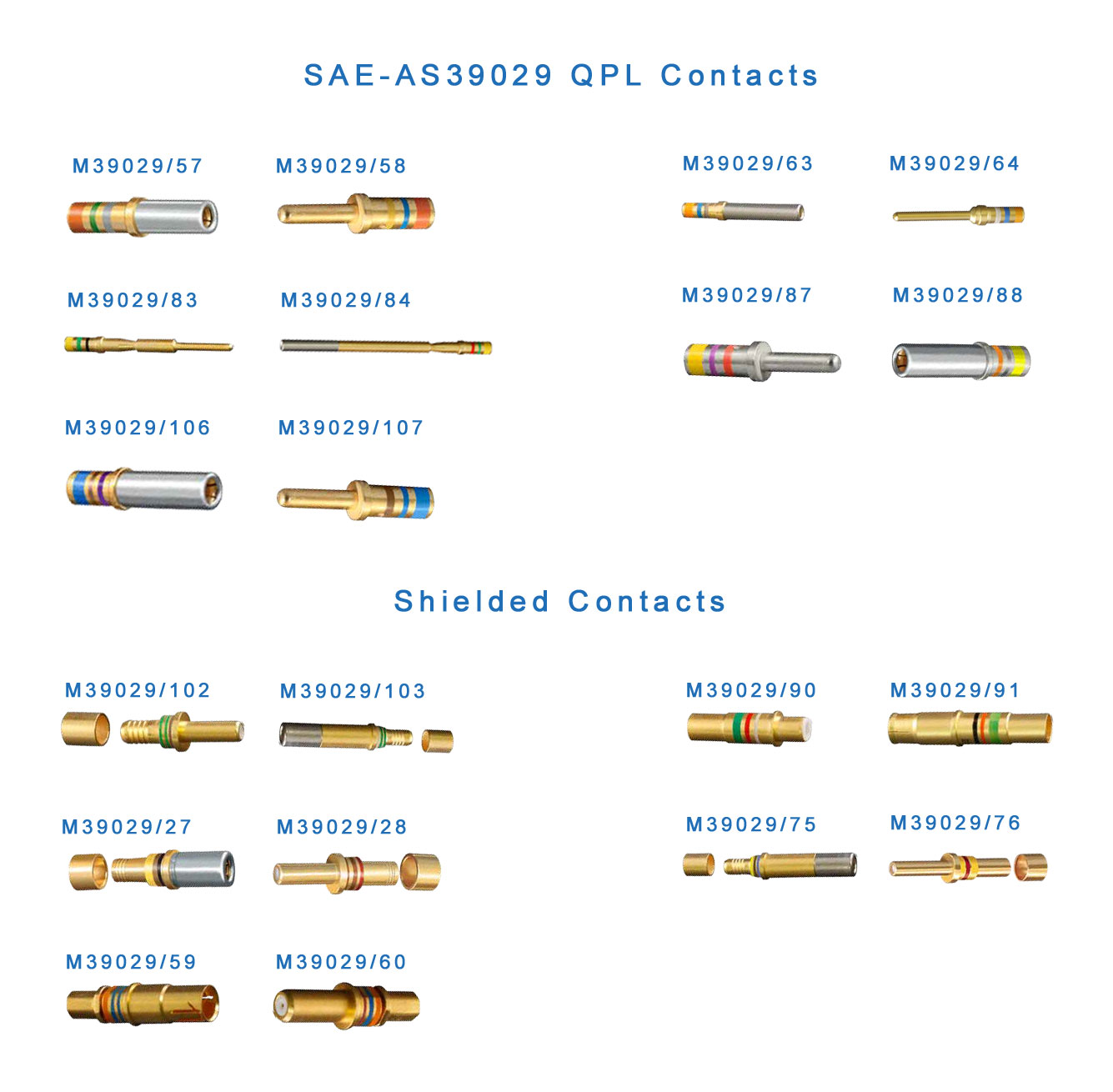
M39029 Contacts are used in D38999 connectors.
Contact Color Codes
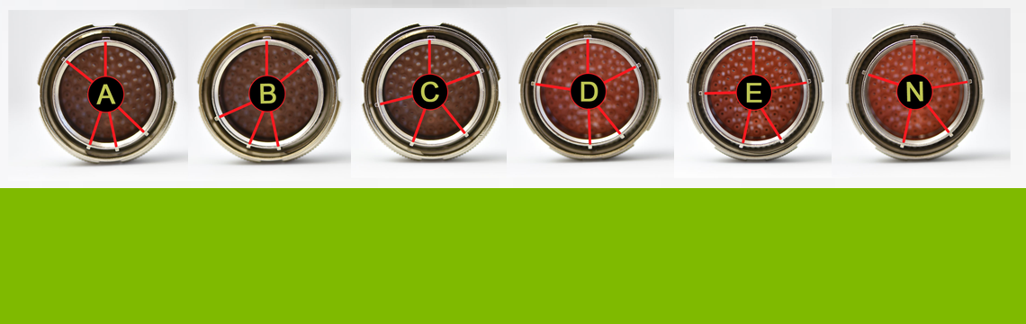
Keying Position

There are six distinct keying positions available for each shell size in the D38999 series of connectors: N, A, B, C, D and E. The keying position is indicated by the last letter in the part number. A plug will only mate with a receptacle with the same keying code. The following figure shows different keying positions for D38999/26FJ61P plug.
Having 6 different keying positions allows use of up to six D38999/26FJ61P plugs in the same space without the possibility of mating a plug with incorrect receptacle.
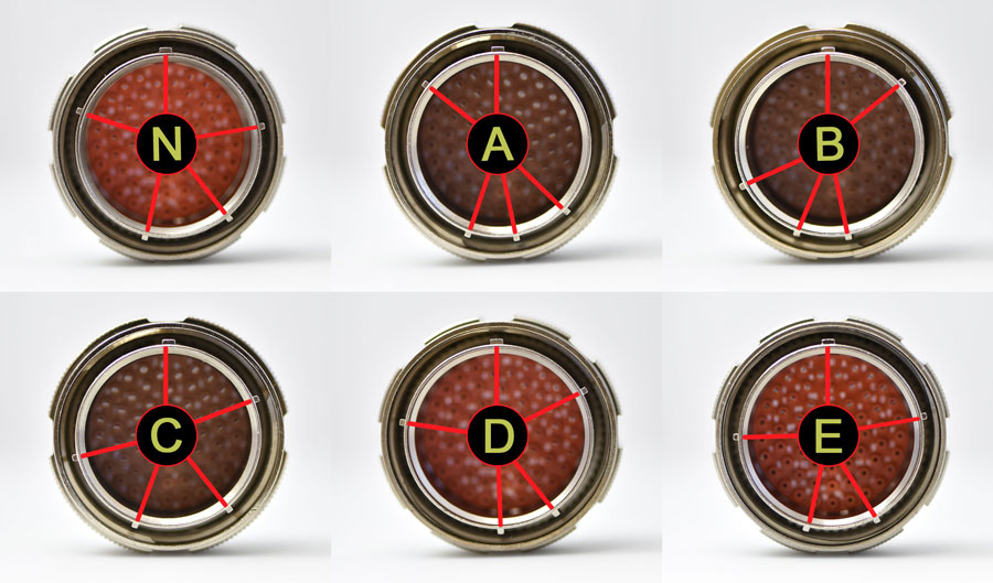
All available keying positions for D38999/26FJ61P
Assembly Instructions
Tools
Wire Stripping
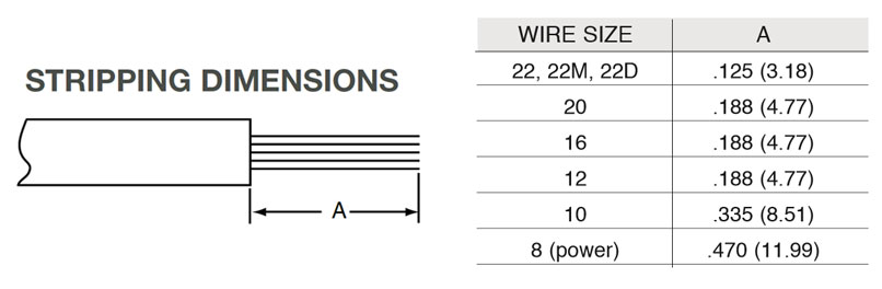
- Strip wire to required length. When using hot wire stripping, do not wipe melted insulation material on wire strands; with mechanical strippers do not cut or nick strands.
- Twist strands together to form a firm bundle.
- Insert stripped wire into contact applying slight pressure until wire insulation butts against wire well. Check inspection hole to see that wire strands are visible. If there are strayed wire strands, entire wire end should be re-twisted. When wire is stripped and properly installed into contact, the next step is to crimp the wire inside the contact by using the proper crimping tool.
Contact Crimping
- Insert stripped wire into contact crimp pot. Wire must be visible through inspection hole.
- Using correct crimp tool and locator, cycle the tool once to be sure the indentors are open, insert contact and wire into locator. Squeeze tool handles firmly and completely to insure a proper crimp. The tool will not release unless the crimp indentors in the tool head have been fully actuated.
- Release crimped contact and wire from tool. Be certain the wire is visible through inspection hole in contact.
Contact Insertion
- First remove hardware from the plug and receptacle and slide the hardware over wires in proper sequence.
- Use proper plastic or metal insertion tool for corresponding contact. Slide correct tool (with plastic tool use colored end) over wire insulation and slide forward until tool bottoms against rear contact shoulder.
- Next align the tool and contact up to the properly identified cavity at rear of connector plug. Use firm, even pressure; do not use excessive pressure. It is recommended to start at the center cavity. Contact must be aligned with grommet hole and not inserted at an angle. Push forward until contact is felt to snap into position within insert.
- Remove tool and pull back lightly on wire, making sure contact stays properly seated and isn’t dragged back with the tool. Repeat operation with remainder of contacts to be inserted, beginning with the center cavity and working outward in alternating rows.
- After all contacts are inserted, fill any empty cavities with wire sealing plugs. (Refer to sealing plug charts for Series III on page 29, for Series I & II and SJT see page 30-31.
- Reassemble plug or receptacle hardware - slide forward and tighten using connector pliers. Connector holding tools are recom- mended while tightening back accessories. When using strain relief, center wires at bar clamp. Slide clamp grommet into position and tighten clamp bar screws. When tightening screws, pressure should be applied in the same direction that clamp is threaded to rear threads of connector. When not using clamp grommet, build up wire bundle with vinyl tape so clamp bar will maintain pressure on wires.
Contact Extraction
- Remove hardware from plug or receptacle and slide hardware back along wire bundle.
- Use proper plastic or metal removal tool for corresponding contact. Slide correct size tool over wire insulation.
- Insert plastic or metal removal tool into con- tact cavity until tool tips enter rear grommet and come to a positive stop. Hold tool tip firmly against positive stop on contact shoulder. Grip wire and simultaneously remove tool and contact. (On occasion, it may be necessary to remove tool, rotate 90° and reinsert.)